Full Text
INTRODUCTION
Many straits and passages between ocean basins or regional seas exhibit strong flows that are difficult to observe yet represent important controls or exchange mechanisms for the adjacent regions. Examples are the Denmark Strait in the North Atlantic, the Indonesian Throughflows between the Pacific and Indian Oceans, the Strait of Gibraltar at the entrance of the Mediterranean, and the Yucatán Channel as the source region of the Loop Current in the Gulf of Mexico. In most cases, the subsurface structures of these flows are important, as is density or temperature layering, and in some cases, there is a clear two-layer separation between inflow and outflow layers. These important interior conditions are usually not observable from space or with other remote-sensing methods. Thus, in situ instruments are required.
One example is the application discussed here, the use of bottom-mounted pressure-sensing inverted echosounders (PIESs) to track the vertical structure and the horizontal displacement of the Yucatán Current, where the lateral position is needed with higher temporal resolution than, for example, satellite altimetry can provide. The horizontal displacement of the Loop Current has been related to its growth/decay downstream, westward displacement being associated with Loop Current growth (Manta et al., 2023). Modeling studies show that the deep flow within the Loop Current below 1,000 m, which is not measurable by surface sensing, may also be predictable (Vazquez et al., 2023).
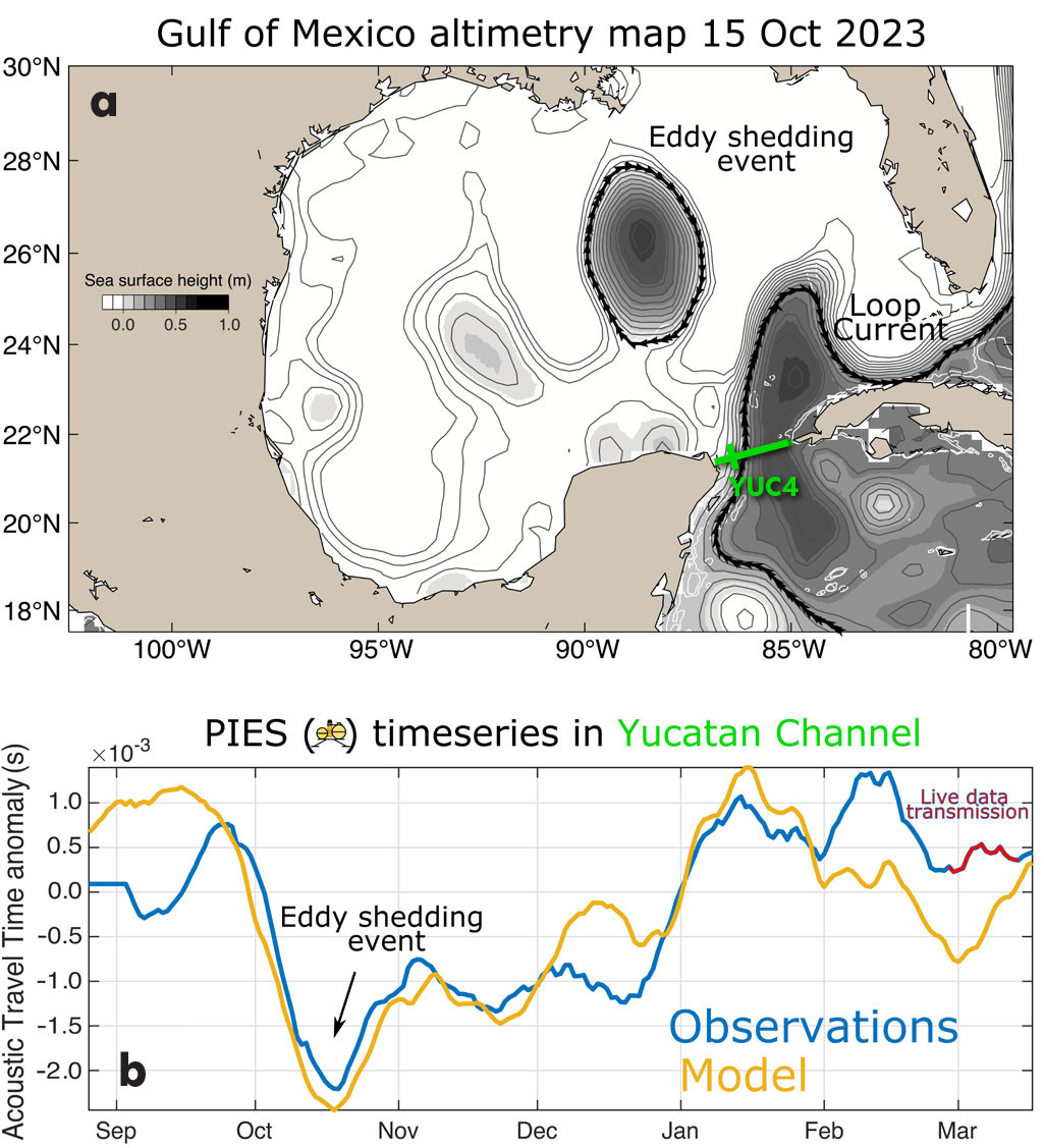
Figure 1a shows a snapshot of the Gulf of Mexico after an eddy-shedding event. Such eddies represent intense flow anomalies that are important for predicting the security of oil rigs operating in the Gulf. In the Yucatán Channel, PIESs measure bottom pressure and vertical acoustic travel time between the seafloor and the sea surface. Preliminary data from a test deployment there show that roughly two weeks before the shedding event, the PIESs measured a continuous reduction in acoustic travel time (Figure 1b). The use case here demonstrates that if real-time data from PIESs were available and fed into numerical models, such event predictions are possible.
|
|
Due to cost and personnel availability, crewed ships are not an option for continuous, year-round data collection on these flows. Equally, autonomous vehicles such as underwater gliders, Wave Gliders, and Saildrones cannot hold position in strong currents. It is also difficult to anchor and maintain a surface buoy in extreme current conditions. The challenge is to find an approach that enables real-time data delivery from subsurface instruments in such strong-flow regimes. Other than laying a cable on the seafloor, the most feasible technology in deep ocean data acquisition is acoustic telemetry. This requires a surface platform to perform underwater telemetry and to relay the data to shore via satellite. Here, we present a simple solution that was developed for currents exceeding 4 knots and demonstrate that data telemetry from bottom-mounted PIESs in such environments is possible.
The application described here is an array of five PIESs spanning the Yucatán Channel at approximately 21°40'N, ranging in depth from 250 m to 1,800 m. This is a challenging environment due to strong currents (often 3–4 kts), the presence of a major shipping lane, and the prevalence of Sargassum seaweed.
MOORING DESIGN
Given these conditions and the possibility of losing the float (e.g., from ship strikes, fish bites, fishing line entanglement), the Yucatán Channel mooring design needed to be simple, low-cost, and easy to deploy, and the surface float had to minimize drag and shed Sargassum. A long cylinder, tapered at both ends, was chosen as the float design because it can tilt in strong currents and is likely to shed Sargassum when horizontal at the surface.
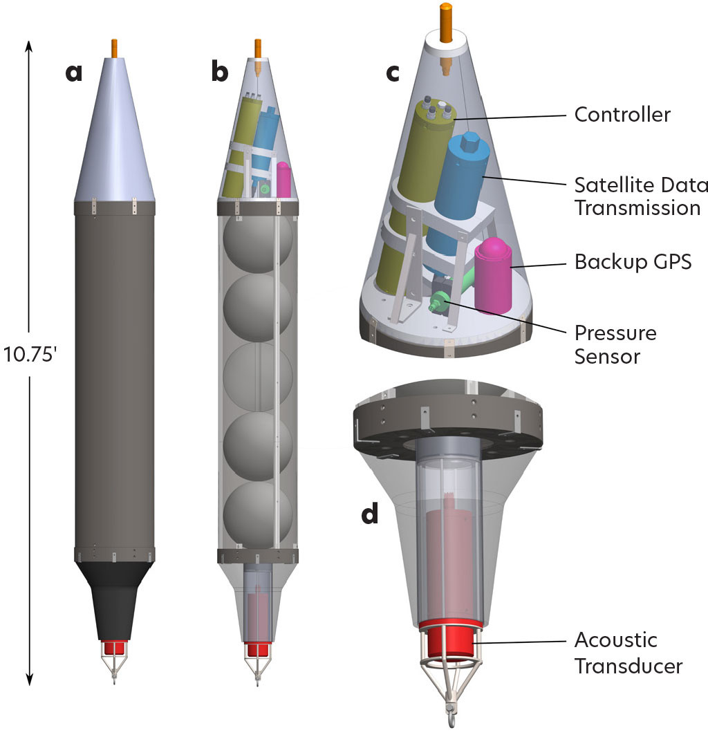
To maximize the use of off-the-shelf components and minimize cost, our design uses several 14-inch fishing trawl floats protected and streamlined by a large 16-inch industrial PVC pipe. The electronics and transmitters are housed under a UV-protective plastic cone at the top of the float, and the acoustic modem is installed inside a self-poured polyurethane cone at the bottom. The Iridium antenna inside the Delrin transmitter pressure case is angled so that it roughly points upward during typical float tilts, and the float has a ballasting weight designed to rotate into the desired orientation. The use of these parts allows for cheap and quick turnaround, as almost everything is made in-house, eliminating potentially long lead times and outsourcing costs. Overall, the final material and machining to produce a single (unloaded) telemetry float cost just under $6,000. With all instruments and electronics (portable acoustic modem, controller, Iridium transmitter, and GPS beacon), the total expenditure was about $27,000. These costs are expected to decrease as more moorings are built, because the largest expenses were incurred for single prototype runs of custom parts or pressure cases. Figure 2 shows the current design for deployment with our custom payload. All components are designed to withstand depths of more than 300 m, because we expect the surface float to be pulled underwater for short periods in the most intense currents phases. This could also help to shed Sargassum.
|
|
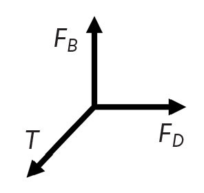
For a steady-state orientation of a mooring surface float in the current, the horizontal drag force (FD) induced by the currents can only be compensated by the horizontal component of the tension (T) on the mooring line below the float. This (downward) tension is determined by the combination of drag and (upward) buoyancy force (FB).
|
|
Therefore, a small buoyancy will lead to a more horizontal mooring line, making it difficult to keep the float at the surface. Because we had already used the largest available trawl floats, buoyancy could only be increased by lengthening the float. However, both the drag and the volume of a (vertical) cylinder in constant flow scale linearly with length. Therefore, the angle of the mooring line is not changed by increasing the cylinder length (only line tension changes). Simulations with a static mooring design program (IMP, updated from Helmbrecht, 2001) confirmed that performance did not change much between using, for example, nine trawl floats or five. Detailed simulations suggested that five floats were a good option. This gave a net float buoyancy with all electronics and hardware installed of 63 kg (80 kg without electronics).
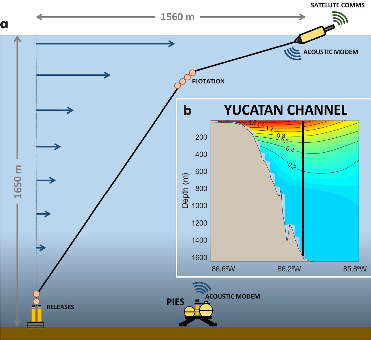
To minimize the drag on the remaining mooring components, we use thin synthetic line (1/8-inch Amsteel) wherever possible. Because the currents in the Yucatán Channel are surface intensified with the strongest currents in the upper 150–200 m, standard 17-inch glass floats can be added below the strong currents without adding too much drag, helping to keep the mooring vertical. Given the drag-buoyancy ratio of the top float, a large mooring tilt of order 70° results, which requires a long line to cover the uppermost water column. The resulting design is outlined in Figure 3 for the test deployment (see below) in 1,650 m water depth. The drag forces are substantial: order 150 kg for the top float, and the tension near the anchor can approach 500 kg. Therefore, the required anchor weight varies between 600 kg and 1,000 kg, depending on water depth.
|
|
TEST DEPLOYMENT
In August 2024, the mooring was deployed for four weeks in 1,650 m of water near a PIES in the Yucatán Channel (Figure 3). This site was next to the YUCi5 mooring of the Canek current meter array established in 1999 (Sheinbaum et al., 2002; Candela et al., 2019). The float typically surfaced twice per day and remained at the surface approximately 75% of the time, despite the Yucatán Current being near peak strength. When the float was knocked down by strong currents, data were still retrieved acoustically, stored, and then transmitted once the float returned to the surface. The float’s ability to reach the surface in strong currents was likely due to tides, which periodically weaken even in the strongest currents. The rate of transmission matched the rate of data collection, giving a truly real-time delivery of PIES data with latencies of fewer than 24 hours. This deployment followed a previous successful test in 500 m of water that showcased the moorings’ ability to perform in varying depths. The two moorings were nearly identical in design, only needing to be scaled up by increasing mooring line length and adding mid-mooring flotation via additional 17-inch glass spheres. The maximum deployment duration of a PIES is four years; we present energy and transmission budgets for the remote modem for this duration below. For shorter deployments, more data can be transmitted.
PIES DATA TRANSMISSION: Data Rates and Energy Budget
Here, we present a data rate and energy budget for the deployment described above to illustrate the capabilities and limitations of typical acoustic modems, using PIESs as an example. These instruments are made by the University of Rhode Island (Kennelly et al., 2022), with a custom modification to output data through a serial port installed in the glass sphere. A Teledyne Benthos acoustic modem (ATM-9 series) with a low-frequency transducer is attached to each PIES so that data can be recovered acoustically via an underwater glider (Send et al., 2013), from a surface vessel, or via a mooring. The PIES takes one sample every 10 minutes (one pressure and four acoustic travel time readings) and stores the single samples internally, but only sends the last value obtained at the end of every hour to the acoustic modem. This amounts to 597 bytes per day or 217,905 bytes per year. These data are stored permanently in the modem memory and can be downloaded at any time by another acoustic modem located within 8–10 km.
In our application, there will be a mooring with a surface expression that contains a controller interfaced with an acoustic modem and a satellite modem. The controller uses the acoustic modem to download data from the remote PIES acoustic modem, and the data are then both stored internally and sent through the satellite system (Iridium using RUDICS protocol). Each byte takes about 2.12 J to be stored and sent acoustically in average conditions (30 bytes per second selected download speed with a 300 baud setting in the modem), maximum transmission power, and a transmission success rate of 67%. During deployment, the remote modem is in one of four different states, each requiring the following energy over four years (values are given for daily downloads and for downloads every four days):
- Data storing, when receiving data from a PIES via RS-232 (609 kJ per day/609 kJ per four days)
- Link establishment, when a remote modem tries to start an acoustic communication with the PIES modem at the beginning of each download (852 kJ/213 kJ)
- Data transmission, when sending data over the acoustic link to the buoy modem (902 kJ/1,027 kJ)
- Quiescent/sleep mode (1,766 kJ/1,766 kJ)
This energy output would result in about 95% (daily) or 83% (every four days) of the entire lithium battery pack capacity for storing and sending data after four years. In addition, the time needed for sending commands and handshaking reduces the effective download speed, depending on:
- Distance between the acoustic modems
- Retry rate
- Packet size (a data request command needs to be sent for each data packet)
This effective download speed can be estimated as (assuming 1,500 m s–1 average sound speed and 3 s total time for each command to be internally processed by the modems):
|
|
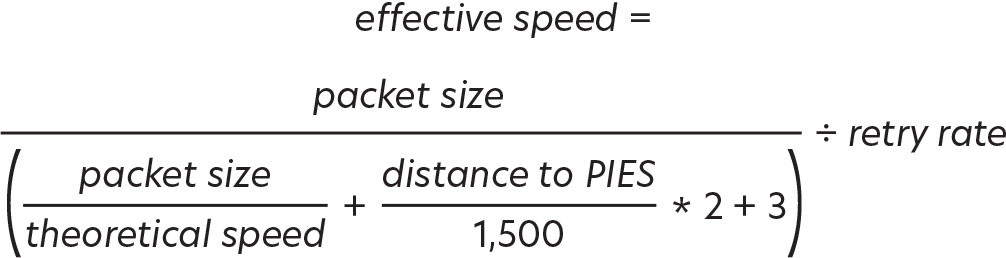
For a typical setup on the Yucatán Channel PIESs, where we conservatively achieve a 30 B s–1 theoretical speed, a distance of 4,000 m, a packet size of 500 bytes, and a retry rate of 1.5, we get an effective speed of 13 B s–1, so less than half the theoretical speed. If we reduce the packet size to 250 bytes, we get only 10 B s–1, one-third of the theoretical speed.
DISCUSSION
Although still in a preliminary design stage, this simple telemetry mooring has demonstrated its potential with several successful test deployments in 500 m and 1,650 m of water, while successfully sending data that have been used for Loop Current predictions. Even in peak flow conditions in Yucatán Channel, the float reached the surface typically twice per day, likely when tidal flows reduced the current speeds a bit. The float is designed for low cost, in terms of both construction and operation, allowing for deployments in larger numbers or with frequent replacements. The entire mooring can be deployed by hand from a smaller boat (the anchor can be tipped into the water with a simple wooden platform). The float also allows for both hardware and software customization to, for example, accommodate different sensor types such as CTDs or pumped optical sensors like fluorometers or oxygen optodes. In the ongoing project in the Yucatán Channel, we have already added data transmission from additional bottom-mounted temperature/salinity sensors, and are considering adding telemetry from bottom-mounted current meters to better characterize the channel’s throughflow. Given the current success, a future cruise has been scheduled for August 2025 to deploy three more floats at various water depths along with current profilers to complete the array and to permit real-time transmission of all our PIES data. While this new design is still being tested and improved, it has successfully demonstrated remote data acquisition in harsh environments with modest hardware investment: near-continuous, real-time data from far beneath the strongest ocean currents can indeed be collected. This advancement opens the door for real-time data applications from deep-water sites that were previously inaccessible.
ACKNOWLEDGMENTS
This work was supported by the Gulf Research Program of the National Academies of Sciences, Engineering, and Medicine under award numbers 2000011057 and 200013145.